



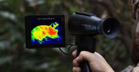

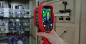
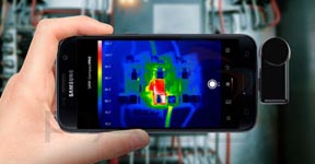
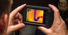
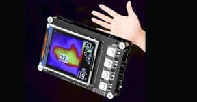


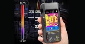





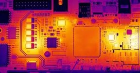

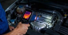
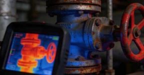
Thermal Imaging Analyzers have become indispensable tools in the field of electronics inspection and maintenance, especially for PCB (Printed Circuit Board) analysis. They allow engineers to visualize temperature distribution across circuits, identify hotspots, detect faulty components, and improve design reliability. However, achieving accurate and consistent results requires more than just turning on the device. Proper operation, calibration, and environmental control are essential to ensure reliable thermal analysis.
1. Ensure Proper Calibration Before Each Use
Before conducting PCB inspection, it’s crucial to calibrate the Thermal Imaging Analyzer properly. A slight miscalibration can cause inaccurate readings and lead to false conclusions about component performance. Always perform a quick check using a known reference temperature source or follow the manufacturer’s recommended calibration routine. Regular calibration also compensates for sensor drift that may occur after extended use.
2. Control Ambient Temperature and Lighting Conditions
Environmental factors such as room temperature, airflow, and lighting can affect infrared readings. For PCB testing, it’s best to perform measurements in a stable, temperature-controlled environment. Avoid direct airflow from air conditioners or fans, as these can cause inconsistent surface cooling. Likewise, reflective lighting or metallic surfaces can introduce thermal noise that interferes with precise analysis.
3. Maintain a Clean and Stable Test Surface
Dust, grease, or oxidation on the PCB surface can alter thermal emissivity and distort readings. Before testing, ensure the board is clean and free from contaminants. Use non-abrasive cleaning materials and allow the surface to dry completely. When placing the PCB on the analyzer platform, make sure it’s level and stable to prevent vibration or heat dissipation inconsistencies during imaging.
4. Understand Emissivity Settings
Every material emits infrared radiation differently. Metals, plastics, and solder joints each have unique emissivity values. Using incorrect emissivity settings can lead to significant temperature reading errors. When analyzing PCBs, pay attention to mixed-material surfaces and adjust emissivity values accordingly. Many analyzers allow users to manually input emissivity data for more accurate temperature mapping.
5. Avoid Overheating the Sample
When using thermal excitation or power-on testing, overheating can damage delicate PCB components. Always monitor the heat input and limit exposure times. If you’re using the analyzer in combination with a power supply or heating element, ensure thermal safety limits are set. A good practice is to start from a lower current or voltage level and gradually increase it while observing real-time thermal patterns.
6. Choose Appropriate Resolution and Sensitivity Settings
High-resolution and high-sensitivity settings provide detailed imagery but can also increase data noise if not properly configured. For PCB inspection, balance clarity and data stability. Fine details are valuable when analyzing small components or micro-solder joints, but for broader thermal profiling, moderate sensitivity might yield cleaner results. Adjust these parameters based on your inspection goal.
7. Interpret Thermal Patterns Correctly
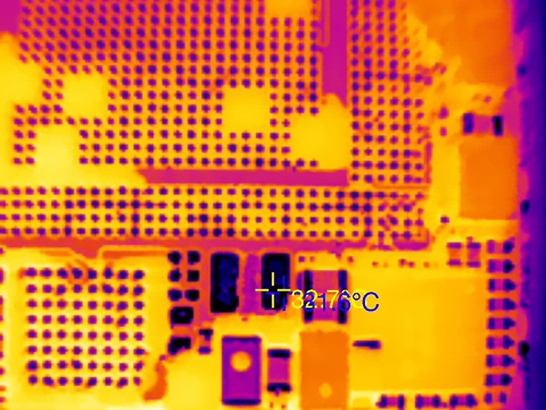
Thermal anomalies on a PCB do not always indicate defects. Some components naturally operate at higher temperatures. It’s essential to interpret thermal maps within the context of the circuit design. Compare readings to reference boards or simulation data to distinguish between normal and abnormal heat signatures. Misinterpretation can lead to unnecessary rework or incorrect fault identification.

8. Keep the Lens and Sensor Clean
Infrared sensors and lenses are sensitive to dust and fingerprints, which can degrade image quality. Always clean the lens using soft microfiber cloths and appropriate cleaning solutions. Avoid touching the sensor directly. For analyzers with detachable optics, store them in protective cases when not in use to prevent contamination or scratches.
9. Record and Archive Test Data Systematically
Thermal analysis is most valuable when data can be compared over time. Save temperature maps, thermal videos, and inspection reports in an organized format. This allows engineers to track component performance trends and identify degradation patterns early. Many modern analyzers offer built-in data export functions — make use of them to maintain a reliable inspection archive.
10. Regularly Update Software and Firmware
Software updates often include improved image processing algorithms, enhanced calibration functions, and bug fixes. Regularly check for firmware and software updates to keep the analyzer performing at its best. Updated tools can also provide better compatibility with analysis software and offer new visualization features for more detailed inspections.
Conclusion
Using a Thermal Imaging Analyzer for PCB inspection goes far beyond capturing a thermal image — it’s about accuracy, consistency, and care. By paying attention to calibration, environment, emissivity, and handling procedures, engineers can obtain highly reliable data that leads to better designs, faster troubleshooting, and improved electronic performance. Proper use not only ensures better results but also extends the lifespan of both your device and the components under test.